(reprinted from MIX Magazine, Vol. 10, No. 8)
Magnetic heads: ah yes, those small blocks of metal with a million wires sticking out the back are probably, inch for inch, the most expensive real estate on your tape recorder. Why are they so expensive? Why do they wear? How long do they last? And a question often asked, What are they?
In order to appreciate and understand the answers to these and other questions concerning magnetic heads, one must recognize the intricate role these components play in the overall recording process. Considering how many different tape machines and track formats are involved throughout the entire analog production process (from the studio to the finished duplicated product), it is obvious that a periodic head maintenance program is essential to insure quality recordings. Magnetic head design and manufacturing has become a science in tightening tolerances, extending performance capabilities and developing new products and materials, while attempting to meet the current production requirements at both the equipment manufacturing and end user (replacement) levels.
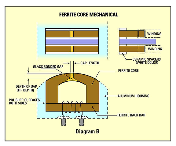
A majority of multitrack and mastering recorders today utilize a form of laminated Mu-metal core construction for record and playback heads (see diagram A). Erase heads, and an overwhelming majority of high-speed tape duplicator heads, are manufactured of various formulations of a ferrite material, often referred to as glass heads (diagram B).
Click on a diagram to see a larger, clearer version in a new window.
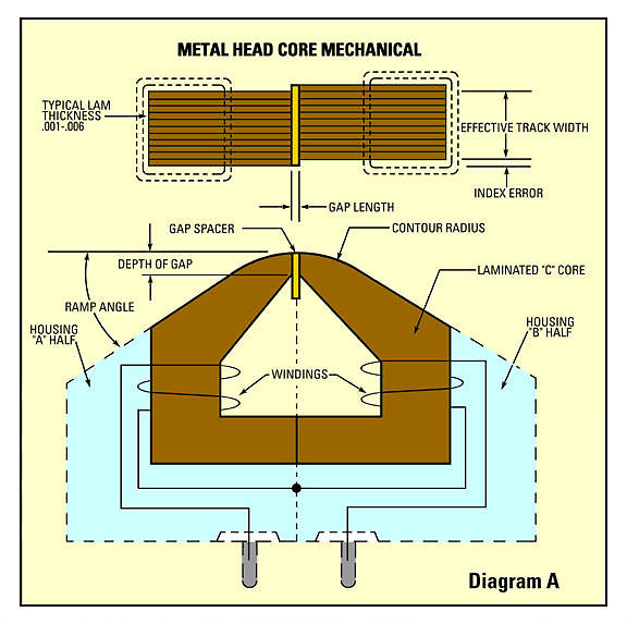
In both metal and ferrite head design, careful consideration is given to the choice of materials that comprise the critical tape contact area. Considering that this area of a metal head consists of laminated mu-metal cores, laminated shields, gap, epoxy and housing materials, equal hardness and abrasive resistance is of major importance to insure even wear characteristics.
To aid in even and consistent wear (edge-to-edge), all metal heads manufactured today incorporate edge relief slots. These machined slots are located outside the edge tracks and within the minimum width tolerances of magnetic tape specifications. In practical theory, magnetic heads with edge relief slots are far less susceptible to uneven edge wear problems caused by variations in tape widths and the razor sharp edges generated in the tape slitting processes. Edge relief slots are rarely used in ferrite head construction due to the long wear characteristics, hardness, and edge chipping susceptibility of the material.
As illustrated in diagram A, metal heads are constructed in two (mirror image) halves, each containing "C" laminated cores. The mating inner surfaces of the two halves must be lapped and polished flat to insure consistency in gap length, inductance and, particularly in multi-channel heads, gap scatter and phase. Great care is exercised in this process to not workharden or destroy the surface permeability of the cores within the mating surfaces. Poor handling at this stage can effectively make a head assembled with a 100 micro-inch gap perform electrically as if it had a 200 micro-inch or greater mechanical gap. In general, most quality heads manufactured today exhibit about 10 to 20 micro-inches of work hardening within their mating surfaces, and this figure is calculated into the size of gap spacer specified in the head design.
Assembly of the two halves, particularly core registration of indexing alignment (i.e. left of gap core alignment with right of gap core) is very important. While exact alignment is ideal, most quality heads are built to within a .001 index error. (Refer to diagram A).
As evidenced by diagram B, ferrite head design and construction techniques are totally different from that of metal heads. Due to its extreme hardness and composition, ferrite material is very brittle, and great care must be taken in the choice of mating materials, glass bonding, assembling, machining and the finishing processes so as not to incur stressing. Since ferrite does not flex, problems such as cracking and chipping are a result of material stressing and usually appear during manufacturing.
One of the most misunderstood terms is that of glass bonded ferrite. Glass bonding is a critical timing, temperature, and atmospheric control process that forms the gap and bonds the two "L" cores together. In this procedure, the two "L" cores are shimmed apart by the gap length desired. Temperature is brought up slowly to in excess of the melting point of the glass and held for about an hour. During this peak temperature period, liquid glass flows into the shimmed gap cavity area and bonding takes place. The entire process, including the cooling period, takes between six and eight hours.
Much like magnetic tape, many different compositions of ferrite material are used in a wide variety of magnetic head applications. Most of the heads manufactured for audio recording utilize a composition of manganese-zinc, which possesses the highest permeability and greatest stability characteristics.
Head manufacturing is a complex balance of machining delicate materials while keeping the alteration of their electrical properties to a minimum. Equipment manufacturers specify exacting electrical and mechanical parameters to which heads are produced. Finished tolerances in magnetic heads vary from manufacturer to manufacturer. However, in general, most fall within the following specifications:
Inductance: ± 15 percent
Gap length: ± 5 percent
Tip depth: .012 minimum
Track width: ± .001
Track to track (ctr/ctr) location: ± .001 (non-accumulative)
Core lamination thickness: .001-.006 (metal heads)
It is important to note that as a head wears, the inductance drops proportionally. As a general rule, when a head is worn out (tip depth within .001 of going through) inductance will usually measure about 60 percent of the initial (new) reading. Since output is a function of the number of turns and efficiency of the core material, level will not drop as a result of the reduction of inductance.
Since all recording equipment is designed and manufactured around the operation characteristics of new magnetic heads, a good maintenance program is essential in preserving optimum performance. Magnetic heads and assembly tape guides on many tape machines are the only non-rotating contact surfaces within the tape path. As tape passes over the heads with sufficient wrap and tension to insure intimate stable contact, the inevitable result is going to be head wear in one form or another.
Head wear is directly related to:
1. Tape Passage (in feet): the operational speed of the tape machine, particularly the volume of tape passing over the heads, must be considered when looking at head wear. Often overlooked, a machine operated at 30 ips will pass twice as much tape over the heads as a machine used at 15 ips. Within the same period of time, the 30 ips machine will obviously exhibit greater wear.
2. Tape Tension: this (user adjustable) variable can be devastating to the expected life of magnetic heads. Under normal use, light adjustments are usually made to compensate for tape-to-head contact losses caused by head wear. Never should the tension be adjusted to exceed the recommended specifications of the equipment manufacturer. It should be noted that after head reconditioning, it is very important to readjust (reduce) tape tensions to the minimum acceptable setting.
3. Tape Path Cleanliness: everything in the tape path including heads, guides, rollers, lifters, capstan, pinch rollers and posts should be kept as clean and free of debris as possible. Heads should always be cleaned in a horizontal (or tape passage) motion and never up and down. In some types of heads, an up/down cleaning motion will cause lamination spreading and breakdown.
4. Tape Abrasiveness: this is for the most part an unknown value that varies between tape types and from tape manufacturer to manufacturer.
5. Environmental Conditions: As a general rule, tape recorders are comfortable when we are comfortable. While optimum settings may vary in different parts of the country, in general temperature should be kept between 68 and 72 degrees; and humidity 30 to 50 percent. Typical tape handling problems related to climate control conditions can include oxide shedding, oxide sticking to heads, tape path instability, static, poor tape winds, and excessive head wear.
As a magnetic head wears in normal operation, certain conditions and minor problems develop that indicate a gradual deterioration in performance. On metal heads, the symptoms are a result of minor changes in contour and tape-to-head contact loss caused by wear. These include: signal amplitude instability, slight loss of high frequency, and unstable tracking or tape path.
Ferrite record and playback heads, due to the extreme hardness and composition of the core material, do not wear as conventional metal heads do. Slight losses in high frequency response are generally the early indications of core surface and gap deterioration caused by material erosion (head wear).
Variation or change in performance caused by wear is usually very slight and normal EQ and/or minor transport alignment compensation will maintain operational consistency and spec.
Ferrite erase heads are often regarded as indestructible and never in need of attention. While their operational properties usually do not vary, wear does take place and problems develop, thus signaling erase head deterioration. In conventional erase head construction, the edges of each track and the guard band area with shields between the tracks, contain epoxy or glue lines that hold everything together. Non-core or shield areas are made up of a softer non-magnetic material such as brass, aluminum, copper, or barium titanate (ceramic). Over time, as the guard band material wears, the ferrite edges on some or all of the tracks (and shields) fracture and break down, producing small chips and sharp edges along these surfaces. This condition is visually almost undetectable without the use of a microscope. Early warning signs will show up as small areas of oxide buildup either on the erase or record heads. A worn erase head is a major contributor to oxide shedding problems within the head assembly.
The question is often asked, when is it time to refurbish or replace tape heads? Since the definition of acceptable performance varies between individuals, facilities, applications, and quite often, economic considerations, the answer is very subjective. As a general rule, heads and assemblies should be refurbished at, or prior to, the point at which maintaining operational spec is in question. If wear is allowed to continue, minor problems can become major ones, and alignment is no longer possible. Major symptoms include:
- oxide shedding and excessive buildup
- dropouts
- loss of high frequency response
- midrange bump
- distortion
- noise
- unstable signal and tape path
- tracking error
- edge track instability on multi-track heads
- insufficient erasure
It should be noted that a ferrite record or playback head in serious need of refurbishing will show no obvious wear pattern, groove, or change in contour (as compared to metal heads.) Upon close visual inspection of the tape contact area, a matte or dull finish is noted as compared to the high polish non-contact area. Under a microscope, the dull finish reveals a surface deterioration and pitting at and around the gap area. This surface breakdown alters the surface gap length and definition (sharpness). The procedure of relapping, recontouring, reprofiling, refurbishing and so on, performed properly, restores a magnetic head to its original specifications. Strict adherence is paid to maintaining original contour, ramp angle, gap/crown centering, and end to end crown radius consistency. Zenith, or tilt 90 degree reference to mounting surface, and precision finishing is essential.
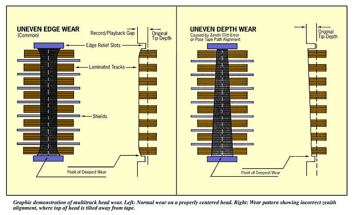
The two diagrams below illustrate the most common wear patterns found on metal heads. These same wear conditions are typical on everything up to two-inch multitrack head stacks. Assuming that the contour is consistent end to end, the widest wear area is always the deepest.
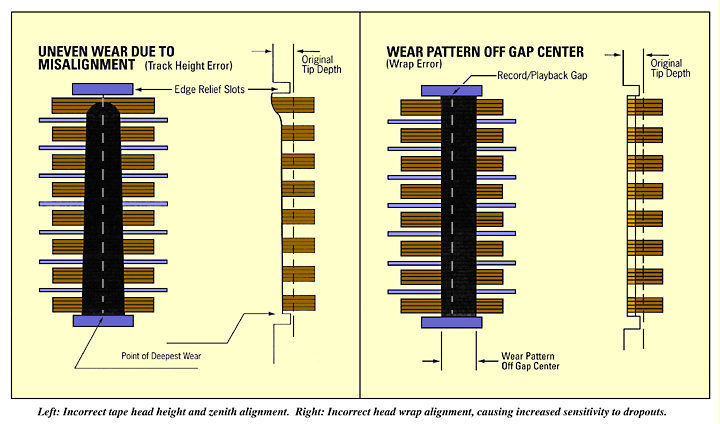
Most uneven wear conditions are the direct result of tape path problems and/or head misalignment. The four drawings below represent wear patterns caused by misalignment. As a general rule, metal heads will usually wear slightly deeper at the edges. This is due to tape tension and curl effect of magnetic tape (as shown on the top left drawing).
Click on either pair of drawings to see a larger, clearer version in a new window.
Since tip depth is directly proportional to dollars, removal of the absolute minimum amount of material in the refurbishing process is of major concern. For example, a $2500 multi-channel head with a .010 (ten thousands of an inch) tip depth means that every .001 (one thousandth) of depth is valued at $250.
Electrical and mechanical analysis, which consists of inductance, DC resistance, Q, measured gap depth, wear depth, initial contour and wear pattern is an important part of head refurbishing. A complete analysis must be performed prior to and after relapping. It is this information, coupled with documented wear characteristics, design data on the specific magnetic head, and tolerances which enables accurate performance and expected life estimates. Considering that the cost of refurbishing ranges from 5 to 25 percent of replacement, the savings are substantial.
An important part of a refurbishing program includes the precision head mounting and optical alignment of the entire head assembly. Since a large percentage of head problems stem from tape path and/or initial head misalignment, it is very important to start with a known reference when re-installing new or refurbished heads. Our procedure of Optical Alignment includes a thorough cleaning, wear analysis and any required repair, replacement and realignment of all tape path components on the head assembly. Fixed tape guides, roller guides, wear posts and flutter idlers should be cleaned, rotated to a fresh tape contact surface (if non-rotating), set to the exact OEM reference height and aligned for perpendicularity and parallelism. Magnetic heads are Installed and aligned for exact track placement (within .0005 to edge of tape location). Azimuth, zenith, and track placement is aligned with the use of high powered optical viewing and digital measuring equipment. Head wrap is set for gap centering on the scrub or wear pattern.
The reinstallation of a properly refurbished and optically aligned head assembly usually requires only a minor azimuth adjustment (for phase alignment) and the standard electrical adjustments. Tape tension must be checked and adjusted (reduced) to the minimum acceptable setting. The time saved in the studio for mechanical installation can be substantial.
Often times, the overall effects of normal head wear, and various minor misalignments within the tape path, result in the machine being only slightly out of alignment. Head wear in one form or another, is a gradual, long term, but continuous process, which in many cases goes unnoticed. The requirements and demands for higher quality analog recording grow each year. It is hoped that the information contained in this article will help in the understanding of magnetic heads and the benefits of a good maintenance program. •